
 In the Projects section of the website, we mentioned how it is sometimes a necessity for rail lines to drop quite steeply within a confined area. We have capitalised on the tight radius-of-curvature and the increased gradient to produce the double-helix track configuration. This double-helix has been a key element to allow CF Technologies rail solutions in congested dock areas, and a cornerstone of our submissions to several port operators.
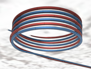
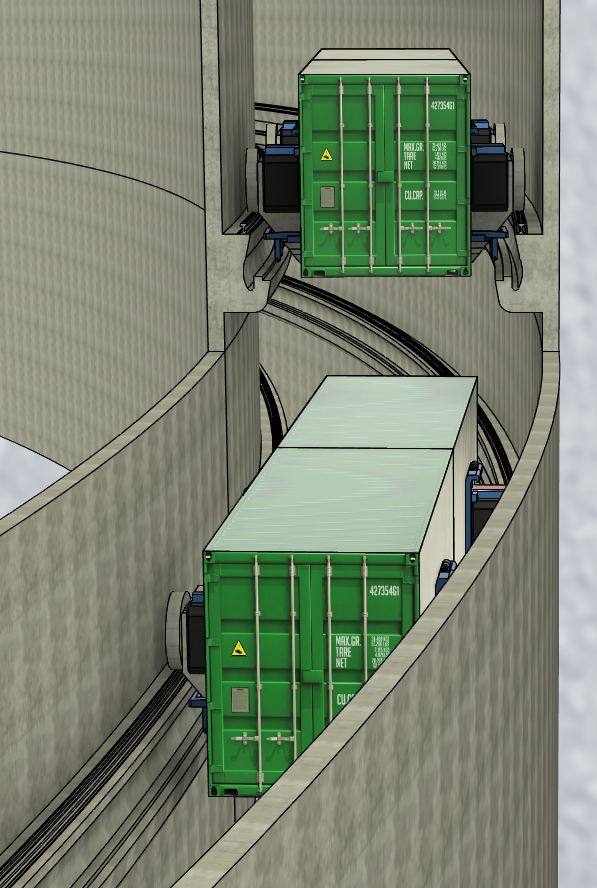 In the image above, the double-helix is represented as two interwoven helical pipes, not really a practical implementation. The original design specification describes a practical construction technique where the double-helix is installed within an open cylindrical shell that goes to full depth. This would allow quite a variety of construction options. In addition, there could be a few maintenance shafts for later use.
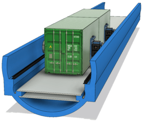
Within the shell, supports would be inserted on both sides at regular intervals. The width of the shell is approximately equal to the diameter of the pipes, 5 metres, allowing ample room to install supports into the surrounding soil or rock. The sides of the shell could be lined by stacking prefabricated blocks in place, the blocks being shaped to hold both the rails and the power-lines.
This configuration creates an opportunity to introduce some novel construction techniques. Construction might begin with a circular gantry around the perimeter of the shell. Front-end loaders could circle around below the gantry, getting ever deeper on each revolution. The gantry would then be used to hoist excavated soil to the surface.
Also required in the final installation, although not shown in the illustration, are the light, open-mesh flooring panels that would separate the various levels. This flooring is not essential for normal operation of the container-vehicles, but is extremely important for the safety of construction and maintenance workers.