CFT Innovation Key Features

Pipe-Rail Model

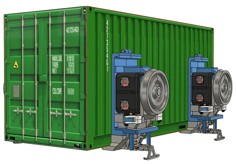
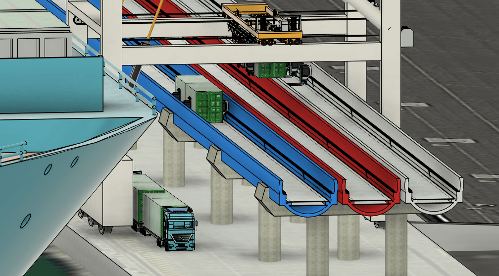
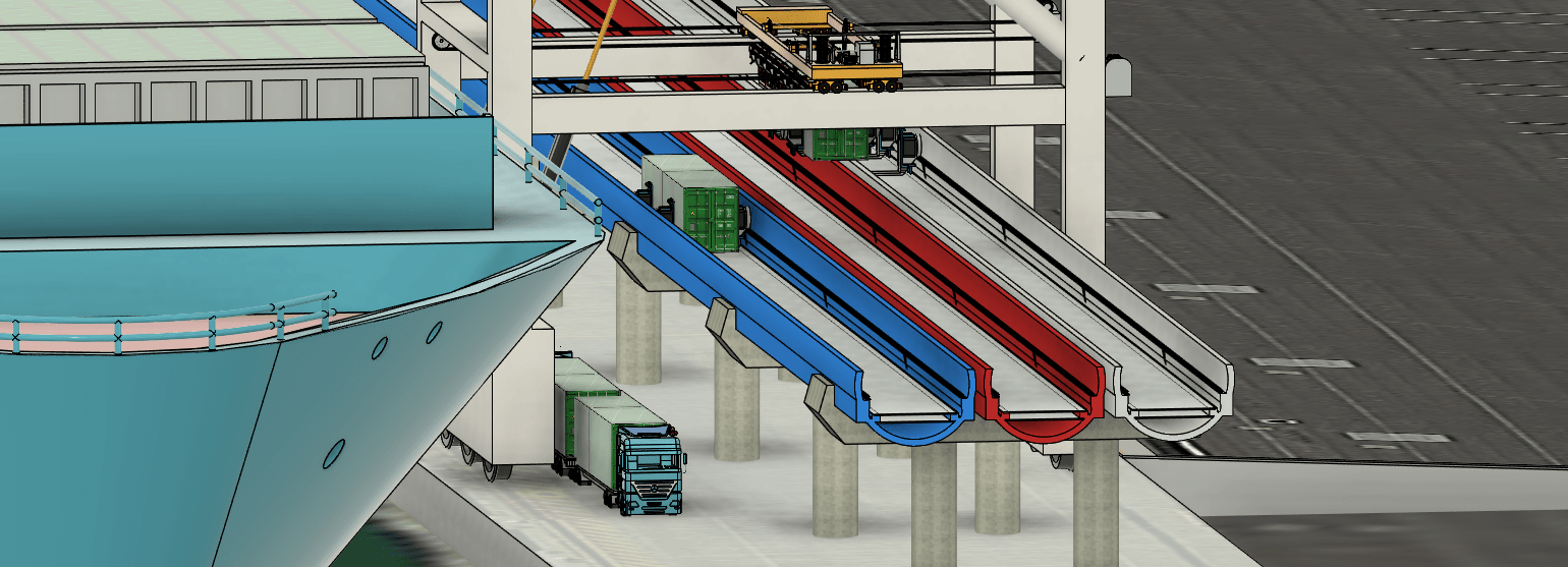
Central to the CFT design is the requirement of maximum flexibility.  It should be possible to run vehicles at ground level while still in a pipe; it should be able to run above ground similar to SkyRail; and it should also be able to run underground when appropriate for the terrain.  An early part of the design specified that the system be encased in a pipe. There are several advantages related to this.

At ground level, a system encased in a pipe has a relatively small footprint because the separation strip between the rail and its surroundings can be reduced to a minimum.  Noise is also minimised.  As with all electrified rail systems, pollution levels are almost non-existent, at least at the point of delivery.  In addition, the pipe design is well suited to tunnels whenever the track needs to be routed underground.

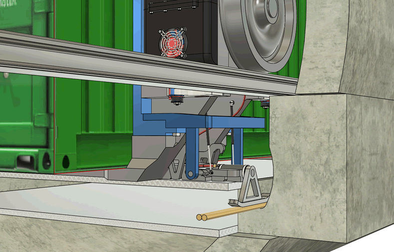
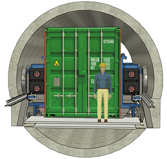
A major consideration during the early phase of the design was to analyse the cost-benefit relationship.  It was important to determine which elements of the design were the best candidates for efficiency tuning so as to maximise value for all phases of the project — installation, operation, plus maintenance and refurbishment during its lifetime.  One parameter identified as extremely critical, was the pipe diameter.  Small variations in pipe diameter rippled through various aspects of the design and had a significant impact on installation costs.  A key part of the early investigation was to determine the minimum tunnel diameter that would accommodate the larger 40-foot containers, while allowing for cornering and access for maintenance.

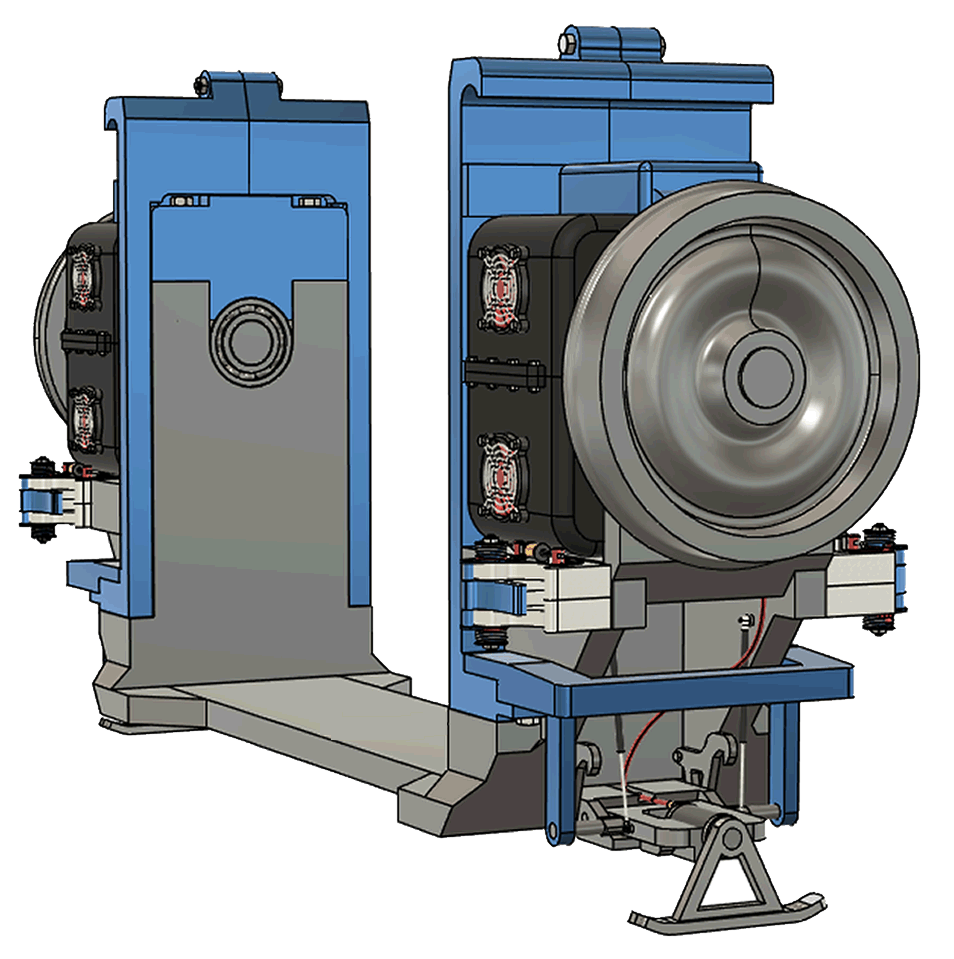
After much research into the way companies around the world handled containers in tunnels, there appeared to be no design that made full use of the tunnel cross-section.  Most designs fell back to the traditional model with the wheels below the container.  One or two implementations were a little more creative with the use of conveyor systems, but the evidence suggests there were serious limitations that prevented wider use of the technology.

Container as a Vehicle

The breakthrough for CFT was the realisation that, from a geometrical perspective, the wheels and motors were best placed halfway up the sides of the container.  The concept was simple; the engineering a little less so.  It took over a year of serious effort to refine the design to a point where it made good engineering sense.

The end result is that each container becomes a rail vehicle in its own right when four wheels and four motors are attached around the sides.  Each combination of two motors and two wheels is referred to as a Detachable Drive Unit or DDU.

Adding two DDUs to a container creates a ‘Container Vehicle’.  Using the container body to form a structural part of the vehicle keeps the weight of the transportation component to an absolute minimum.

Detachable Drive Units (DDUs)

A unique feature of the CFT design is to attach wheels and motors to each container so that the container-structure becomes the body of the vehicle.  This minimises the overall weight of the vehicles and thereby reduces the power requirements.

Each pair of wheels on a U-shaped frame is called a Detachable Drive Unit or DDU.  The DDUs have a subtle mechanism for attachment to the containers — the weight of the container will force the DDU to clamp to the container sides.  When a container is lowered onto a pair of DDUs, they are automatically held together until the container is lifted again.

The circumference of the pipe is significantly less when the wheels are placed on the side of the containers rather than underneath.

Third-Rail Power Supply

The next stage of the design involved the evaluation of various techniques that could supply power to the Container-Vehicles.  In the distant future no doubt, batteries or some other mechanisms will be available to provide on-board power.  However, for the foreseeable future the best solution is likely to use a power-line for energy supply.  This could involve an overhead catenary connection, or be underneath in a third-rail configuration.

The third-rail option was chosen, where shoes extend from the DDUs and make contact with power-lines half buried at both sides of the pipe.  The reason for this decision was driven in part by the requirement that Container-Vehicles need to be raised or lowered onto the tracks through an open top section of the pipe.  Many technical challenges presented themselves before we developed a practical solution.

Communications and Control

With the drive units in place and a mechanism for power delivery, the next step was to determine the best method for controlling them.  The specification as it currently stands calls for container-vehicles to be semi-autonomous.  They will be in permanent communication with a central control, but the amount of data exchange is small with a low refresh-rate.  Information exchanged includes the Container-Vehicle advising its speed and location, while central control will relay details of required destination plus location and speed of the nearest vehicles on the rail line.  The Container-Vehicles will use this information to determine the actions required to reach their destination quickly and safely.

There is one aspect of the data requirement mentioned above, that may not be obvious.  It is vitally important to know accurately where each Container-Vehicle is positioned.  GPS techniques are not suitable below ground, so it was necessary to find a simple and inexpensive alternative.  RFID tags placed every two or three metres along the pipes could be accurately calibrated at the end of the construction phase.  Software on the DDUs would then be able to accurately calculate position using details of which RFID tags were nearby.  That calculation could also be made at the control centre — all DDUs need to communicate is the identity of the nearest RFID tags.

Multistage Gantries

For the system to work, it required an efficient mechanism to assemble the containers and the DDUs together to form Container-Vehicles.  Key to the success of CFT is a modification that can be made to any standard ship-to-shore crane.  In addition to the main gantry which moves the containers with a Spreader, there are two secondary gantries.

The reason for these secondary gantries is twofold – firstly they unite the containers with DDUs so they can be placed on the pipe-rail, and secondly they split container handling into two stages. The promise for this latter design innovation is that it should reduce ship load or unload times by around 20 percent.

The process of combining containers and DDUs is complicated by the fact that the DDUs are not always located at specific positions on a container, and it is necessary to cater for both 20-foot and 40-foot container lengths.  To minimise attachment time, the specification calls for sensors that can determine the desired configuration in advance, and set DDU positioning as appropriate.

Grappling Mechanism

For lifting the container with the DDUs attached, there is a grappling system that grasps the whole unit without any need to adjust for variations in DDU positioning.  This reduces the time spent handling a particular unit, and minimises the possible impact on nearby rail traffic.  The grappling system has tight restrictions because it needs to fit between an open-topped pipe and the Container-Vehicle.

Dockside Container Transfer Facility

There are three open-top pipe channels shown running next to the ship.  Red and blue channels are for container traffic in each direction, and the white channel is a ‘supply’ channel used for storing and feeding the Detachable Drive Units to the gantries when they’re required for unloading containers from the ship.

Would You Like to Discover the Possible Benefits from Applying Our Technology to Solve Your Logistics Problems?